Home

agy érzékelő Orvosi műhiba heat pump ts diagram Csináld jól Vesuviushegy Egyszerű

T-S diagram of heat pump cycle[6]. T-s diagram of heat pump cycle is... |  Download Scientific Diagram
T-S diagram of heat pump cycle[6]. T-s diagram of heat pump cycle is... | Download Scientific Diagram

T-s diagram for heat pump cycle. | Download Scientific Diagram

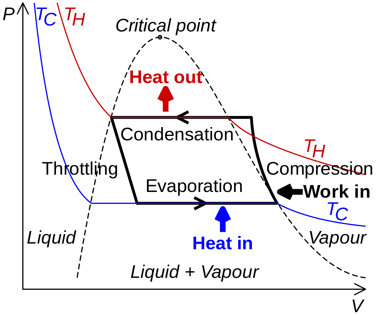
Vapor-compression refrigeration - Wikipedia

Transcritical CO2 heat pump | Industrialheatpumps.nl

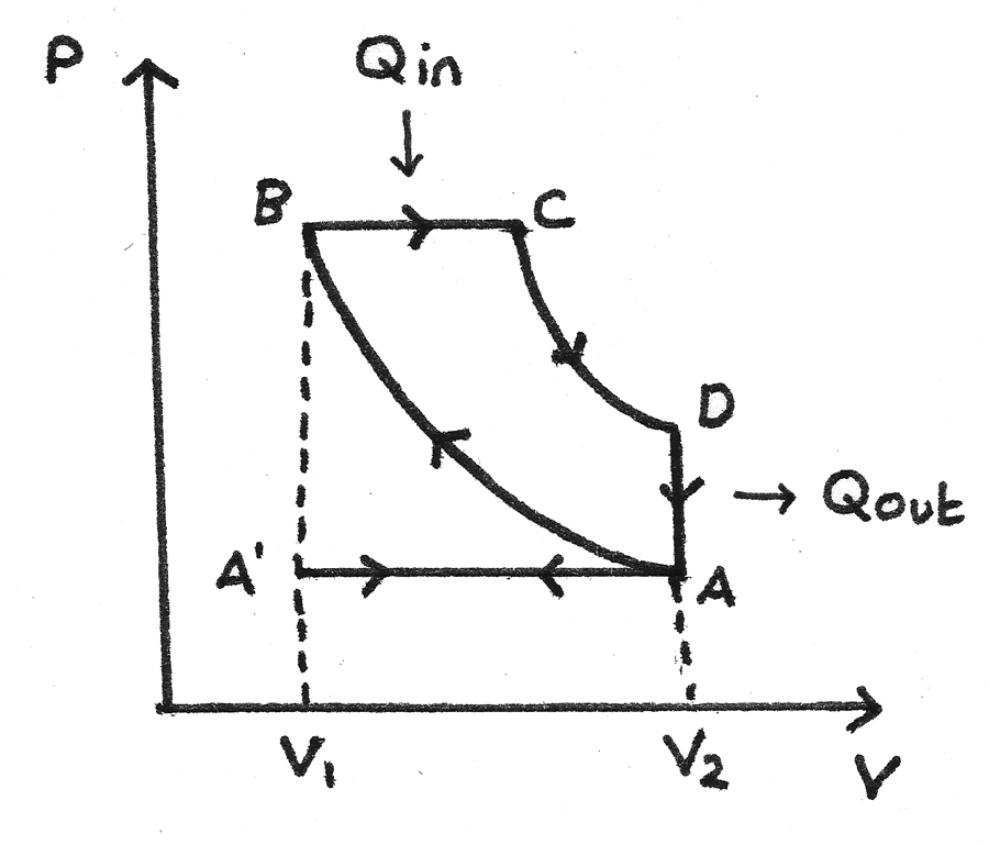
Engines and Heat Pumps - Revise.im

The T-S diagram of a theoretical heat pump cycle for: (a) Zeotropic... |  Download Scientific Diagram
The T-S diagram of a theoretical heat pump cycle for: (a) Zeotropic... | Download Scientific Diagram

Applications of Thermodynamics: Heat Pumps and Refrigerators | Physics

STEPS: Technology description

T-s diagram for heat pump cycle. | Download Scientific Diagram

The T-S diagram of a theoretical heat pump cycle for: (a) Zeotropic... |  Download Scientific Diagram
The T-S diagram of a theoretical heat pump cycle for: (a) Zeotropic... | Download Scientific Diagram

A vapor-compression heat pump system uses Refrigerant 134a as the working  fluid. The refrigerant enters the compressor at 0.24 MPa, 0 C, with a  volumetric flow rate of 0.6 m 3 /min.
A vapor-compression heat pump system uses Refrigerant 134a as the working fluid. The refrigerant enters the compressor at 0.24 MPa, 0 C, with a volumetric flow rate of 0.6 m 3 /min.

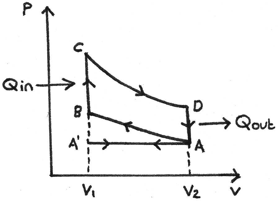
Engines and Heat Pumps - Revise.im

Solved The T-s diagram for a heat pump is given below. A | Chegg.com

a) P-h diagram and (b) T-s diagram of standard heat pump cycle. | Download  Scientific Diagram
a) P-h diagram and (b) T-s diagram of standard heat pump cycle. | Download Scientific Diagram

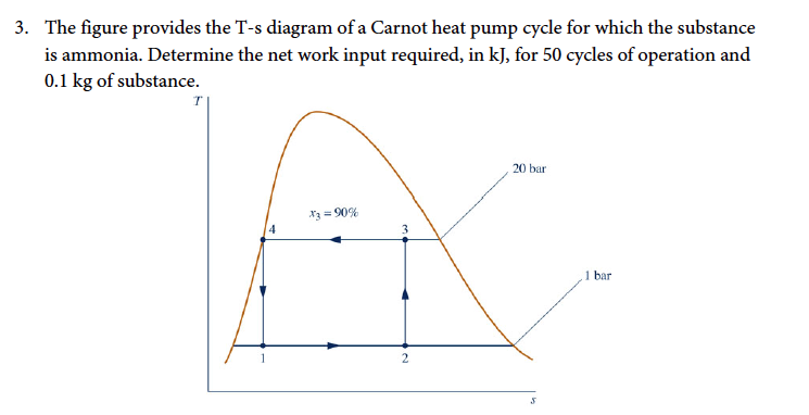
The figure below provides the T-s diagram of a Carnot heat pump cycle for  which the substance is ammonia. Determine the net work input required, in  kJ, for 50 cycles of operation
The figure below provides the T-s diagram of a Carnot heat pump cycle for which the substance is ammonia. Determine the net work input required, in kJ, for 50 cycles of operation

Carnot heat pump (or Carnot refrigerator)

The figure provides the T-s diagram of a Carnot heat | Chegg.com

Property diagrams TS and PH for refrigeration - YouTube

Figure provides the T-s diagram of a Carnot heat pump cycle for which the  substance in ammonia. Determine the net work input required, in kJ, for 50  cycles of operation and 0.1
Figure provides the T-s diagram of a Carnot heat pump cycle for which the substance in ammonia. Determine the net work input required, in kJ, for 50 cycles of operation and 0.1

Ch10, Lesson D, Page 4 - Heat Pump Effciency

Figure 3 from Ground-Source Heat Pumps and Energy Saving | Semantic Scholar

The T-s diagram is of a Carnot heat pump cycle for which the substance is  ammonia. What is the COP of the cycle? Determine the work input required,  in kJ, for 0.1
The T-s diagram is of a Carnot heat pump cycle for which the substance is ammonia. What is the COP of the cycle? Determine the work input required, in kJ, for 0.1

RESCO Site Analysis Project

Solved This figure provides the T-s diagram of a Carnot heat | Chegg.com